Tuesday 29 May 2012

Digital interface working PSK31 on 17m

Here are some screen shots of my homebrew digital interface working. I am running the Ham Radio Deluxe Digital Master 780 software which provides lots of handy functions. The waterfall display and macro options are far better than similar software I have used. As you can see, I have configured the application to send CQ on the 17m band. On the waterfall you will see that I have chosen a low noise area of the band and well away from the strong signal which is left of centre.
Here is my radio gear listening on the central frequency of the band. My digital interface has been labelled so I don’t need to remember the function of each knob. I recently added the Avair SWR/Power meter in-line to provide an analogue view of these values. The LDG antenna tuner also provides similar information but in a less granular digital way.
I have my rig configured so that the ACL is only just starting to activate. This is keeping the TX power output at around 20 to 30 Watts. Over driving the rig causes some interesting issues which I think are due to RF pick-up on the leads. I need to do some further testing with a dummy load and some ferrite cores to prove my theory. My HF antenna is an end-fed wire which isn’t ideal and could be causing some of my problems. For now I’ll keep the power low so that I don’t cause interference.

Tuesday 22 May 2012

USB digital modes interface

The September 2010 addition of the RSGB RadCom magazine, has a simple project for a USB digital modes interface. You can purchase back issues of this magazine from the RSGB website. The article was written by Dave, M5TXJ, and some follow-up information is available on his website HERE. I can’t reproduce the article on this blog due to copyright but here are some images of my construction of this project.

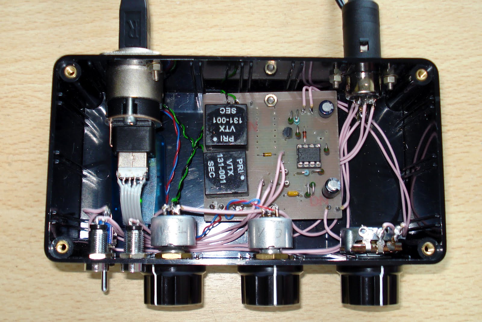
I made the PCB myself by printing the tracks using a laser printer and then ironing it on to a thoroughly cleaned copper clad board. I bought some acid crystals from Maplin and made up the evil concoction in my shed. The etching process took about fifteen minutes.
I was unable to source the relay used by the designer so I used a different type but mounted it under the board.
The USB sound card was sourced from eBay. Because I was using a double sided USB socket in my box, I needed to modify the soundcard to fit in the confined space. The USB plug was easily de-soldered and a short length of ribbon cable inserted.
I’m not a fan of hard wired cables so the box has plenty of sockets.
Here are some images of the internal wiring. I have kept the runs neat and tidy to make maintenance easier in the future.
I found this project easy to build and found most of the components easy to source. The only problem I had was a duff Op amp which once replaced allowed the circuit to burst into life. I hope to upload some video footage soon of this device being used, so keep watching.

Monday 21 May 2012

Building a dummy load

My first self-build project was a dummy load. I collected various circuit diagrams and reviewed various designs but shown below it the one I went with. The box came from Maplin and the remaining components from Farnell and my junk box.
The load described here is capable of handling up to 10 watts of RF power for a couple of minutes, and is designed for the widely used 50 ohms impedance. It consists of ten parallel connected 560 ohms 1 watt resistors, R1 through R10, a voltage divider, R11-R12, and a rectifier D1-C1. Apart from loading the transmitter output with a minimum of reflected power, the dummy load also provides a direct voltage output to which a voltmeter may be connected to measure the RF power. If the dummy load is used for power levels higher than 10 watts simply use more or higher wattage resistors to give a total of about 50 ohms. For instance, by using twenty 2 watt 1,200 ohms resistors instead of R1-R10 and 150 ohms resistors for R11 and R12, the dummy load is turned into a 40 watt version. The diode may be almost any Schottky type. Types like BAT85 and HSCH1001, for instance, are also suitable. Even a germanium type like the AA119 will work, but then for low powers only.
As illustrated, the ten 560 ohms resistors are soldered in a circle around the centre pin of the BNC socket. Their ground terminals are soldered flush to the inside of the case. Capacitor C1 is a feed through type for which a small hole must be drilled. All resistors should be mounted with the shortest possible lead lengths to keep the reactive component of the dummy load as small as possible. After mounting the parts, the cover is fitted on to the case. Do not drill ventilation holes because that will defeat the purpose of making a non-radiating load. The case may get quite hot when transmitter power is applied for a while but that is no cause for concern. Allow the case to cool between tests.

Friday 18 May 2012

Avair AV-601

As I’m hoping to go mobile in the near future, I thought it would be a good idea that I buy a suitable SWR meter. I wanted one that would cover both low and high frequencies. The one I went for was the Avair AV-601. I’ve only just unboxed it so once I can find or make a patch lead, I’ll be trying it out. First impressions are that it is well made with no sharp edges or cheap plastic trim. It would have been nice to have had N-Type connectors for the VHF sockets as I’ll have to use a converter. Here is a picture of the new device.